
RS 2400 - Wireless Headphones SENNHEISER - Free user manual and instructions
Find the device manual for free RS 2400 SENNHEISER in PDF.
User questions about RS 2400 SENNHEISER
0 question about this device. Answer the ones you know or ask your own.
Ask a new question about this device
Download the instructions for your Wireless Headphones in PDF format for free! Find your manual RS 2400 - SENNHEISER and take your electronic device back in hand. On this page are published all the documents necessary for the use of your device. RS 2400 by SENNHEISER.
USER MANUAL RS 2400 SENNHEISER
natural_image
Line drawing of a wireless router device with antenna and control panel (no text or symbols)
natural_image
Line drawing of a TENNHEISER earband device with adjustable neck and ear (no text or symbols on the device itself)Instructions for use 13
Notice d'emploi 23
natural_image
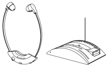
Line drawing of a pair of electronic devices, one with earbuds and the other a speaker tower (no text or symbols)RS 2400
text_image
Diagram illustrating the installation steps of a device with labeled components including earphones, pliers, and TV connections.natural_image
Isometric line drawing of a smart home or smart room layout with connected devices and surrounding trees (no text or symbols)text_image
Diagram showing hands holding a tool with a blue arrow indicating direction, next to a labeled diagram of a device or component.
text_image
SENNHEISER CHANNELEINSCHALTAUTOMATIK
natural_image
Hand holding a wire clamp device with labeled component (no text or symbols on the device itself)natural_image
Line drawing of a pair of electronic devices, one with earbuds and the other a speaker tower (no text or symbols)RS 2400
Thank you for choosing Sennheiser! We have designed this product to give you reliable operation over many years.
Please take a few moments to read these instructions carefully, as we want you to enjoy your new Sennheiser product quickly and to the full.
AREA OF APPLICATION
With the RS 2400 stethoset receiver system you can listen to high-quality stereo TV sound without disturbing others. The RS 2400 has been specially designed for this purpose but can also be used with any other sound source fitted with a headphone socket.
FEATURES
• Lightweight stethoset receiver, comfortable to wear
- Ease of use
- Receiver powered by environmentally friendly NiMH rechargeable accupack
• Volume can be set directly on the receiver
- Transmitter with special charging compartments for simultaneously charging an accupack inserted in the receiver and an additional spare accupack
- Plug-in mains unit available for different mains voltages
• Transmitter with special AF input filter to protect against interference
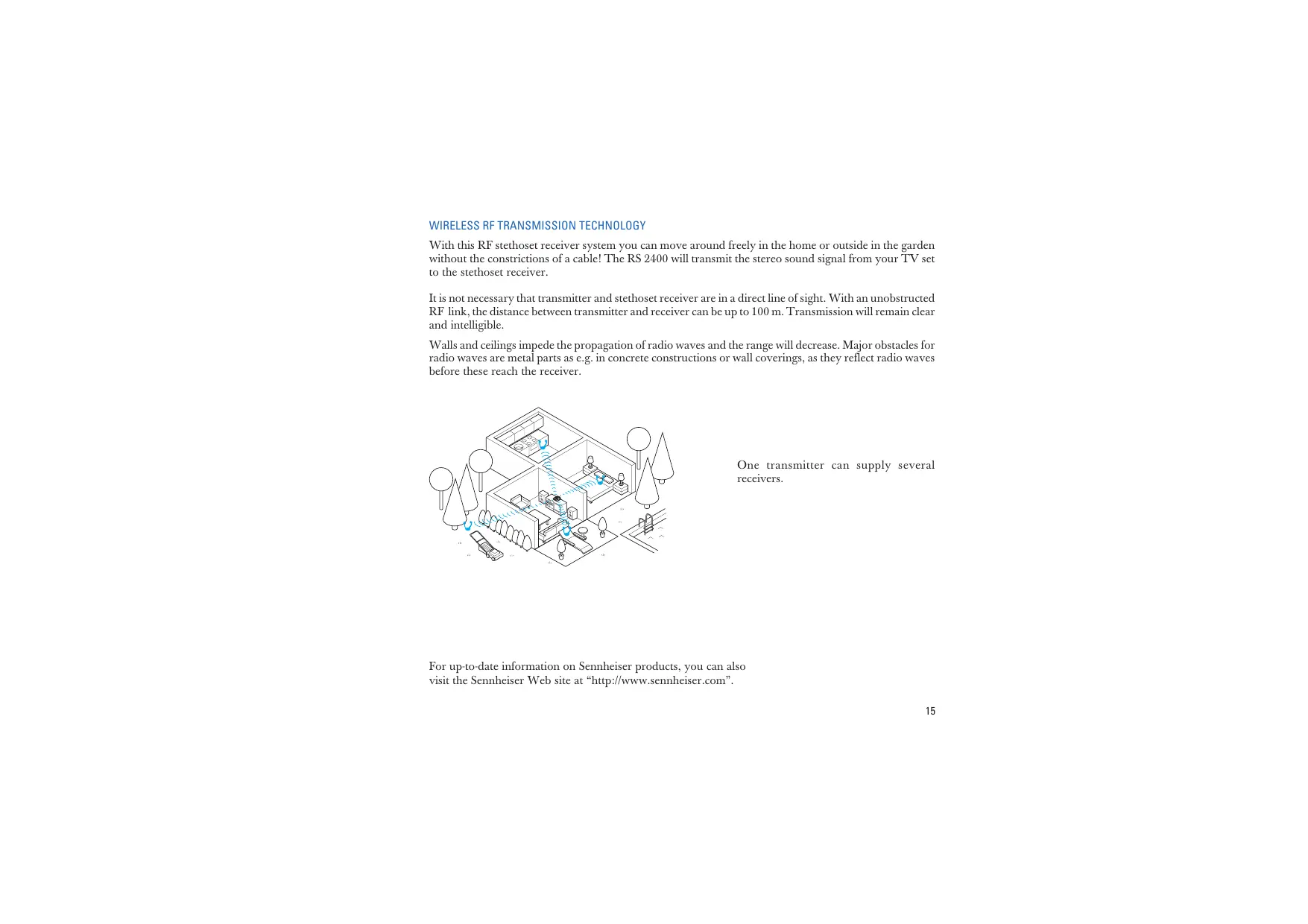
SYSTEM COMPONENTS AND OPERATING ELEMENTS
text_image
Diagram illustrating the installation steps of a device with labeled components including earphones, pliers, and TV connections.WIRELESS RF TRANSMISSION TECHNOLOGY
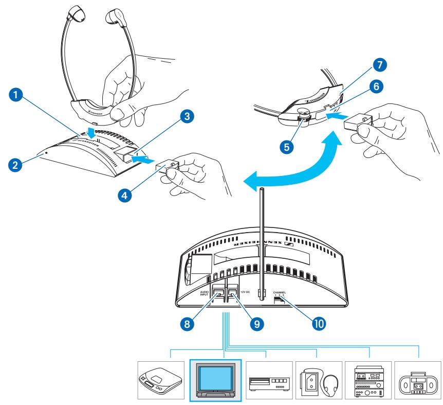
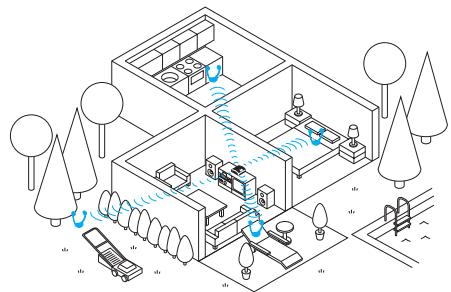
With this RF stethoset receiver system you can move around freely in the home or outside in the garden without the constrictions of a cable! The RS 2400 will transmit the stereo sound signal from your TV set to the stethoset receiver.
It is not necessary that transmitter and stethoset receiver are in a direct line of sight. With an unobstructed RF link, the distance between transmitter and receiver can be up to 100 m. Transmission will remain clear and intelligible.
Walls and ceilings impede the propagation of radio waves and the range will decrease. Major obstacles for radio waves are metal parts as e.g. in concrete constructions or wall coverings, as they reflect radio waves before these reach the receiver.
natural_image
Isometric line drawing of a smart home or smart room layout with trees, lighting fixtures, and a car (no text or symbols)One transmitter can supply several receivers.
For up-to-date information on Sennheiser products, you can also visit the Sennheiser Web site at “http://www.sennheiser.com”.
WHERE TO PLACE THE TRANSMITTER
Choose a suitable place near your TV set.
ATTENTION!
Some furniture surfaces have been treated with varnish, polish or synthetics which might cause stains when they come into contact with other synthetics. Despite a thorough testing of the synthetics used by us, we cannot rule out the possibility of discolouration, since we don't know your furniture. You should therefore always place the transmitter on a non-slip pad.
Use the supplied cable to connect socket 8 on the transmitter to the headphone socket of your sound source. The cable is fitted with a 3.5 mm jack plug suitable for most headphone sockets. For connection to 1/4" (6.3 mm) headphone sockets, use the supplied adaptor.
Connect the plug-in mains unit to socket 9 on the transmitter and plug the mains unit into a wall socket.
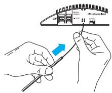
ANTENNA
The wire antenna is an integral part of the transmitter. For best transmission the antenna should be vertical. You can therefore
▶ leave the wire antenna dangling in a vertical position down behind the transmitter or
(the better option) slide the supplied plastic tube over the antenna and snap it into the clamp at the back of the transmitter.
Make sure that there are no metal objects such as shelf bars or lamp stands in parallel with the antenna. Do not place the transmitter on your TV set as it might interfere with the transmitter. Test where exactly in the room the transmitter works best.
The transmitter features a convenient automatic on/off function. When an audio signal reaches the transmitter, it is switched on and the LED ② at the front of the transmitter lights up green. The LED ② also indicates that an accupack is being recharged. When a stethoset receiver or an accupack is inserted into a charging compartment, the LED lights up red.
$$ \text { Green LED } = \text { Transmitter ON } $$
$$ \text { Yellow LED } = \text { Transmitter ON, Accupack recharging } $$
$$ \text { Red LED } = \text { Accupack recharging } $$
$$ \text { LED not lit } = \text { transmitter OFF } $$
If there is no audio signal for about 3 minutes, the transmitter automatically switches off. The transmitter is now in stand-by mode, its power consumption is very low so that it can remain connected to the mains.
IMPORTANT
The transmitter's charging function (charging compartments 1 and 3) is independent of the automatic on/off function. Accupacks can always be recharged when the transmitter is connected to the mains.
When you are not going to use the transmitter for some time (e.g. when you are on holiday), you should unplug the mains unit and take the stethoset receiver and the accupack out of their respective charging compartments.
ADJUSTMENTS ON YOUR TV SET
Please refer to the instruction manual of your TV set to find out whether the volume control also adjusts the headphone output or whether this output has a separate volume control. You will also find instructions on how to switch off the main loudspeakers.
OPTIMUM MODULATION LEVEL OF THE TRANSMITTER
▶ First, set the volume of your TV set to a medium value.
Charge the accupack for 24 hours before you use it for the first time!
Take your stethoset receiver out of the charging compartment 1 on the transmitter.
Have you charged the accupack separately from the stethoset receiver?
Then insert the accupack into compartment 6 in the receiver.
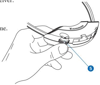
SWITCHING ON THE RECEIVER
Use control 5 to switch on the receiver and adjust the volume.
ADJUSTING THE RECEIVER CHANNEL
Transmitter and receiver have to operate on the same frequency:
Put the transmitter and the receiver into operation as described above. Switch on the TV set! If possible, switch off its loudspeakers.
▶ Use switch 10 on the transmitter to select a transmission channel.
▶ Set the volume control ⑤ on the receiver to a medium value (position 3–4).
Slowly turn control ⑦ (“TUNE”) on the stethoset receiver until you can hear the audio signal loud and clear. The receiver’s AFC (Automatic Frequency Control) circuitry stabilises your adjustment.
Transmitter and receiver are now operating on the same frequency.
text_image
Tension 5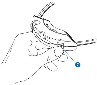
text_image
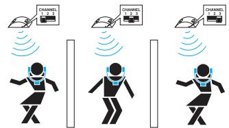
Diagram showing a hand holding a tool with labeled parts, including 'ZscRNA' and number '7'Your neighbour also likes listening with radio headphones? No problem! With switch 10, you simply select a different transmission channel on each transmitter. Then set the stethoset receivers to the respective frequencies (with control 7, as described above). Observe a minimum distance of 2 m between two transmitters.
Due to the required approval two channels are selectable:
text_image
Diagram showing four identical robot figures with 'CHANNEL 1.3' labels above each, each emitting a sensor or signal to the left.Positions 1 or 3 = channel 1 Position 2 = channel 2
IMPORTANT!
Only use the transmitter with a suitable Sennheiser mains unit. Always disconnect the mains connector when you wish to change connections or move the device to a different place.
▶ Never open electronic devices! This must only be done by authorised personnel and is all the more valid for repairs on current-carrying units.
Keep the system away from central heating radiators and electric heaters. Never expose it to direct sunlight.
▶ Use the system in dry rooms only. Transmitter and plug-in mains unit should always remain indoors. You can use the stethoset receiver outside if the weather is dry.
Use a damp cloth for cleaning the transmitter and the stethoset receiver. Do not use any solvents. For reasons of hygiene, the ear-cushions can be cleaned with soapy water. We recommend, however, to simply replace them (inexpensive replacement ear-cushions are available as accessories).
▶ Vanish or furniture polish may degrade the rubber feet of the transmitter. Place the transmitter on a nonslip pad to avoid potential staining of furniture.
VOLUME UP? - NO!
When people use headphones, they tend to choose a higher volume than with loudspeakers. Listening at high volume levels for a long time can lead to permanent hearing defects. Please protect your hearing, Sennheiser headphones also sound exceptionally good at low volumes.
WHAT TO DO IF ...
... the volume is up but you cannot hear anything:
... the sound is distorted:
... the sound is slightly noisy:
... you can hear twittering and chirping, and the sound is “squeezed”:
... the transmitter switches off during operation:
There is no audio signal available. Check the transmitter connection. Is the volume at the headphone socket of your sound source sufficient?
Are you still within the transmitter's range?
Is the receiver on the same frequency as the transmitter?
The receiver accupack has gone flat, please recharge it immediately.
The volume on the receiver is adjusted too high. Reduce the volume.
You are about to leave the transmitter's maximum range. Soon transmission will be interrupted completely.
The transmitter's modulation level is too low. Increase the volume on your sound source.
▶ Two transmitters are interfering!
Choose a different transmission channel.
The volume on your TV set is adjusted too low. Adjust the volume on the TV set such that the LED on the transmitter blinks occasionally.
ACCESSORIES
BA 151
L 151-2
RR 2400-8
Rechargeable accupack as a spare, for use when the supplied accupack is being recharged.
Charger for recharging two BA 151 accupacks (recommended when more than two stethoset receivers are used with one transmitter).
Additional stethoset receiver
RECHARGEABLE ACCUPACKS HAVE A "CHARGING CYCLE"
The charging time of the accupack 4 depends on how long you have used your stethoset receiver. General rule:
OPERATING TIME x 3 = CHARGING TIME
Example:

listening: 1 hr recharging: 3 hrs

listening: 2 hrs recharging: 6 hrs
listening: 3 hrs recharging: 9 hrs
RECHARGING THE BA 151 ACCUPACK
Do not let the rechargeable accupacks become completely flat. If you do, they will be exhausted and cannot be recharged (“total discharge”). This happens e.g. when flat accupacks remain uncharged for some time. Please observe the three following rules:
If you notice that the accupack is going flat, switch off the stethoset receiver and recharge the accupack immediately. If you have a spare accupack you can use it in the meantime.
Immediately recharge the accupack after each use, no matter whether it is fully or only partly discharged.
▶ Charge the accupack for 24 hours before you use it for the first time!
Please note: With both charging possibilities, the accupacks are also recharged when the transmitter is switched off but remains connected to the mains.
ENVIRONMENT AND HEALTH
Devices powered by rechargeable accupacks are environmentally friendly. This energy source can be recharged many times. Conventional batteries, on the other hand, must be disposed of as special waste after they have been used just once. If an accupack should be defective or has been damaged due to total discharge, it is then recycled – the dealer who sold it to you will take it back and will also supply you with a new, original Sennheiser accupack. (Recycling methods differ in different countries.)
According to today's scientific knowledge, the radio waves emitted by this device are by no means harmful.
TECHNICAL DATA
Modulation
Range
Audio frequency response
THD
Frequency range
RS 2400 SYSTEM
FM stereo
up to 100 m
50-12,000 Hz
< 1 %
see type plate located on the bottom
TR 2400 TRANSMITTER
Power supply
Power consumption
RF output power
Signal-to-noise ratio
Audio connector
Input sensitivity
Weight / Dimensions
12 V DC via plug-in mains unit
approx. 1 VA
typ. 10 mW
70 dB(A)
3.5 mm stereo jack plug + 1/4" (6.3 mm) adaptor
typ. 80 mV, automatic limiter system
approx. 170 g (w/o plug-in mains unit) / 134 x 87 x 33 mm
RR 2400 STETHOSET RECEIVER
Signal-to-noise ratio
Max. sound pressure level
Power supply
Current consumption / Operating time
Weight
65 dB(A)
typ. 110 dB
via BA 151 rechargeable accupack, 2.4 V
typ. 20 mA / approx. 4 hrs per accupack
approx. 45 g incl. accupack
SUPPLY SCHEDULE
1 TR 2400-8 transmitter
1 RR 2400-8 stethoset receiver
1 BA 151 rechargeable accupack
1 plug-in mains unit, 12 V DC, for 230, 120 or 240 V mains voltage
1 connection cable with 3.5 mm / 1/4" (6.3 mm) jack plug adaptor
1 instructions for use
1 plastic tube for antenna
1 pair of replacement ear-cushions
natural_image
Line drawing of a pair of electronic devices, one with earbuds and the other a speaker tower (no text or symbols)RS 2400
text_image
Diagram illustrating the installation steps of a device with labeled components including earphones, pliers, and TV connections.TECHNOLOGIE DE TRANSMISSION SANS FIL
natural_image
Isometric line drawing of a smart home or smart room layout with trees, lighting fixtures, and a car (no text or symbols)LED rouge = accu rechargé
natural_image
Hand holding a wire clamp device with labeled component (no text or symbols on the device itself)UTILISATION SIMULTANEE DE PLUSIEURS SYSTEMES
text_image
CHANNEL CHANNEL CHANNEL Position 1 ou 3 = 1 Position 2 = 2REMARQUES IMPORTANTS
approx. 45 g, accu inclus
CONTENU
natural_image
Line drawing of a pair of electronic devices, one with earbuds and the other a speaker tower (no text or symbols)RS 2400
text_image
Diagram illustrating the installation steps of a device with labeled components including earphones, pliers, and TV connections.TECNICA DI TRASMISSIONE SENZA FILI
natural_image
Isometric line drawing of a smart home with air flow and lighting equipment, surrounded by trees and outdoor furniture (no text or symbols)ACCENSIONE DEL RICEVITORE
natural_image
Line drawing of a hand holding a small electronic device with a labeled component (no text or symbols on the device itself)
natural_image
Hand holding a wire clamp or connector with a blue numbered label pointing to the connector (no text or symbols on the diagram itself)natural_image
Line drawing of a pair of electronic devices, one with earbuds and the other a speaker tower (no text or symbols)RS 2400
text_image
Diagram illustrating the installation steps of a device with labeled components including earphones, pliers, and TV connections.natural_image
Isometric line drawing of a smart home or office layout with trees, lighting fixtures, and outdoor furniture (no text or symbols)text_image
Diagram showing hands holding a tool interacting with a device labeled 'Zusammen' and a blue arrow indicating direction.
text_image
SENNHEISER CHANNELnatural_image
Line drawing of a hand holding a wire clamp or connector (no text or symbols visible)FUNCIONAMIENTO SIMULTÁNEO DE VARIAS SISTEMAS
text_image
Diagram showing three robot-like figures with signal waves and a 2.0-channel channel indicator, likely illustrating wireless or signal transmission.1 receptor RR 2400-8
1 acumulador BA 151
natural_image
Line drawing of a pair of electronic devices, one with earbuds and the other a speaker tower (no text or symbols)RS 2400
text_image
Diagram illustrating the installation steps of a device with labeled components including earphones, pliers, and TV connections.DRAADLOZE GELUIDSOVERDRACHT
natural_image
Isometric line drawing of a smart home or smart room layout with trees, lighting fixtures, and a car (no text or symbols)text_image
Diagram showing hands holding a tool interacting with a device labeled 'Zusammen' and a blue arrow indicating direction.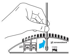
text_image
SENNHEISER CHANNELINSCHAKELMECHANISME
natural_image
Hand holding a wire clamp device with labeled component (no text or symbols on the device itself)MEERDERE INSTALLATIES TEGELIJK IN GEBRUIK
12 V DC via netadapter
ca. 1 VA
typisch 10 mW
70 dB(A)
conform to the basic requirements of EEC Directive 89/336/EEC resp. R&TTE Directive 1999/5/EC. To effect correct application of the requirements stated in the EEC Directives, the following standards were consulted:
Subject to alterations
30900 Wedemark, Germany
www.sennheiser.com
Printed in Ireland
Publ. 07/03
Phone +49 (5130) 600-0
Fax +49 (5130) 600-300
86025 / A02